FTDI USB Drivers download these before you plug in the cable. Not necessary, but many errors can be traced to not using the correct drivers.
The .bin file is the contents of the flash chip from an ECU. It contains the code that tells the ECU how to interpret sensors and run the engine. It contains assembly language instructions along with look up maps and scalars.
The .xdf is a TunerPro specific file that contains the addresses of the maps and scalars for a specific .bin.
The .adx is also a TunerPro file that specifies the format of serial commands between the program and the ECU.
The checksum plugin corrects the binary's checksum after modification. The check sum is a two byte value used to prove to the ECU that the .bin was not modified unintentionally, i.e. corrupted.
The flashing plugin provides the ability to actually flash a modified .bin to the ECU via the VAG-COM cable natively in TunerPro.
Step 1: Download the CheckSum Plugin and place it in your TunerPro RT Directory under Program Files. Note: Unlike many TunerPro plugins, this one will not be shown in the plugins window. It will however be visible at the bottom of the 'Parameter Tree' list when viewing by "Parameter Category'. To verify its installation manually, open a downloaded .bin in a hex editor. Browse to location 1FEFF, and note the value of the next two bytes (this is the checksum). Then, make a single change to the .bin with TunerPro, and save your file. Re-open the .bin with a hex editor and verify the bytes located after 1FEFF have changed. If they have, checksum correction is working properly.
Step 2: Open up TunerPro RT.
Step 3: Go to XDF -> then Select XDF, find the XDF file download and open it.
Step 4: Go to File - > Open Bin, Find the .bin you downloaded and open it. (Hint: in the parameter tree, set the "view by" dropdown to "parameter category".)
Step 5: Go to Acquisition - > Load Definition File and select the ADX file you will be using.
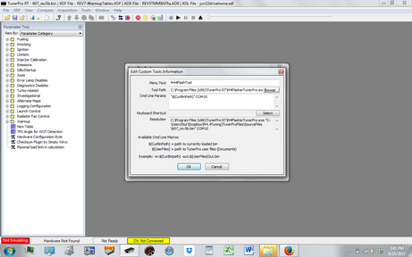
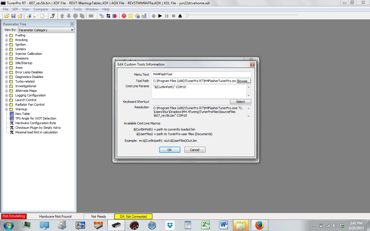
Step 6: Install the Flasher Plugin. Extract the Flashing Plugin .zip (or .rar) and place the 2 files in the TunerPro root folder. In TunerPro, go to Tools -> custom Tools -> Edit Custom Tools. Click New Tool. Give it a name like "Motronic4.4Flasher", then select Tool Path, and select the .exe file you downloaded. Then under Cmd LIne Params add "$(CurBinPath)" COM1 <<<<<Copy and Paste that directly. Change COM1 to whatever Com line you're VAG-COM cable is connected to. Click ok and exit the tools windows.
Step 7: Tuning! Now you can start editing the .bin file to suit your needs.
Step 8: Flash the .bin to your ECU.
Flashing:[]
There are two possible ways to flash the ECU, in the car and on the bench. In order to flash the ECU you must put battery voltage on pin B8 on the ECU (not populated as standard). Having pin B8 at battery voltage when the ECU is turned on causes the ECU to enter bootloader mode, which allows the contents of the flash chip to be erased and written to.
Flashing in the car is theoretically the easiest method to flash the ECU since no custom wiring is needed, however it is hard to maintain battery voltage above 13.5V. If have a powerful battery charger try the flash in car method first. An additional circuit can be created to step up the voltage supply to overcome this issue. See alternative method listed below.
To flash on the bench:[]
Step 1:
You NEED at least a 13.5V source to flash properly. I used 14V, but anything up to 16.8V will work.
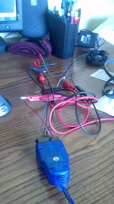
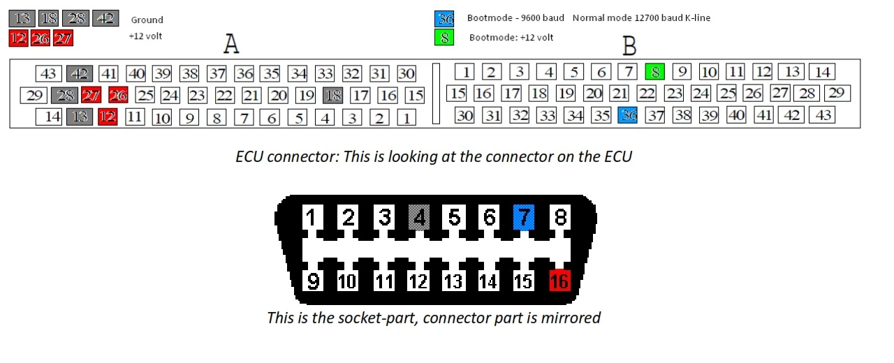
Step 2: Plugin your VAGCOM Cable into your PC. Hook jumper wires to pins 4(ground),7(k-line),16(+13.5v). See picture below for pin-outs.
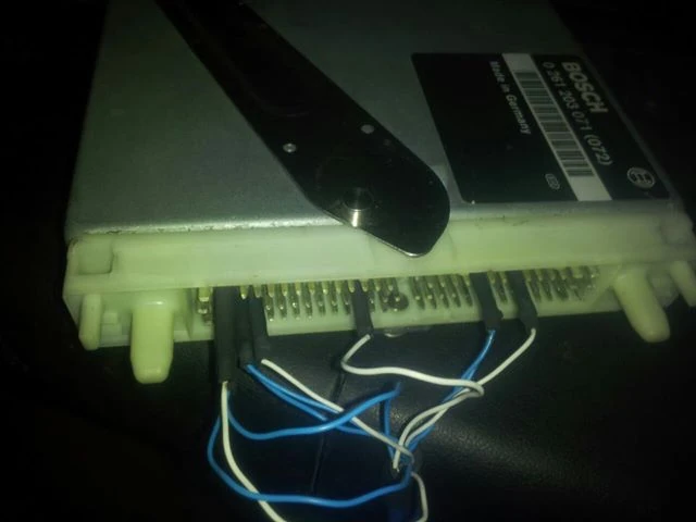
Step 3: Hook up jumper wires to your ECU like the following. Connect power(+14V) to pins A12,A26,A27 on the ECU. Connect a ground to either A13,A18,A28,A42, all ground pins are tied together so only one connection is needed. Connect +13.5V to pin B8 on the ECU (not populated as standard), this is the bootmode pin and will allow the ECU to go into programming mode. Then connect pin 7 of the VAGCOM to pin B36 on the ECU. The ECU must share the same ground and power as the VAG-COM cable!
Step 4: Open up the Motronic 4X flashing utility in tuner pro. Select your binary to flash and click flash, wait for the process to complete. If you have trouble getting your ECU to flash you may need to change some serial settings. Go to Device Manger, Ports (COM), right click on your VAGCOM, click on properties, then go to port settings, advance and set latency timer to 25ms.
Flash in the car (alternative 1):[]
You must figure out a way to engage bootloader mode while the ECU is in the car; you must get above 13.5V on pin B8 (not populated as standard) to be able to flash. There are a few methods of doing this, open the ECU box and wire a switch between pins B8 and A12(ignition power). Or you can solder a long wire to pin B8 and run it to the positive post on your battery. The terminal required to insert into the ECU socket is a "Mini ISO female" also referred to as "Micro Timer", if you are not salvaging a connector and pigtail from another vehicle that is what you will need to purchase.
Connect a battery charger, turn the key to position II and check the battery voltage, if it is above 13.5V you can flash. If the voltage is too low it can help to disconnect the ground wire for the radiator cooling fan, (the fan will run if the ECU is turned on while in bootloader more), and turn off interior lights, radio, and climate control. If you need to raise voltage more, try taking out the fuel pump fuse and other accesory fuses.
Go to Tools/Custom Tools/Edit Custom Tools. Select M44FlashTool - and browse to your selected bin. Make sure your VAGCOM COM port is inserted in the Cmnd Line Parameter (Check DeviceManager if you are unsure of the COM port #). Close the edit tool window. THEN choose Tools/Custom Tools/M44FlashTool and wait for the process to complete. If the battery voltage is below requirements, it will give you an error message. If you have trouble getting your ECU to flash you may need to change some serial settings. Go to Device Manger, Ports (COM), right click on your VAGCOM, click on properties, then go to port settings, advance and set latency timer to 25ms. When flashing has completed, turn key off, disconnect power from pin B8.
Remember to reconnect Cooling Fan, or you will overheat!
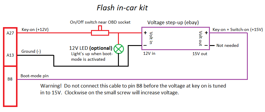
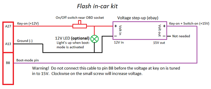
Flash in the car (alternative 2):[]
With this alternative you will be able to flash in the car with just a flick of a switch. The step-up device will increase the voltage to levels above 13.5V without a charger. The battery voltage can remain 12V, only pin B8 (not populated as standard) needs to be above 13.5V to enter boot-mode. Refer to the diagram in order to install the device in the car. I recommend to put the device under the dash and place the on/off switch (+ lamp) near the obd socket. Flick the on/off switch and turn on the ignition. The optional lamp will light up and the radiator fan will start. Adjust the voltage output going to pin B8 to around 15V to be able to flash. You may now start the flashing in tuner pro and when flashing is done you just do key-off and put the switch back to off position. Read the post linked below for more information.
The fan normally runs during flashing but with this guide it will be switched off. The fan control in the ECU works by grounding the pins A7 and A22 for the two speeds (only A22 is active during boot-mode). I did put a relay in the space under the control units to disable the fan while in boot-mode.
This works perfect, no annoying fan under the hood while flashing.
Pinout of a standard 12V relay (A22 will go thru the relay, the cable needs to be cut):
85 = Pin A13
86 = Pin B8
30 = A22 (ECU side)
87a = A22 (harness side)
This will turn off the fan while in boot-mode by "cutting" the A22 cable.